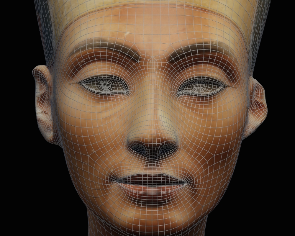
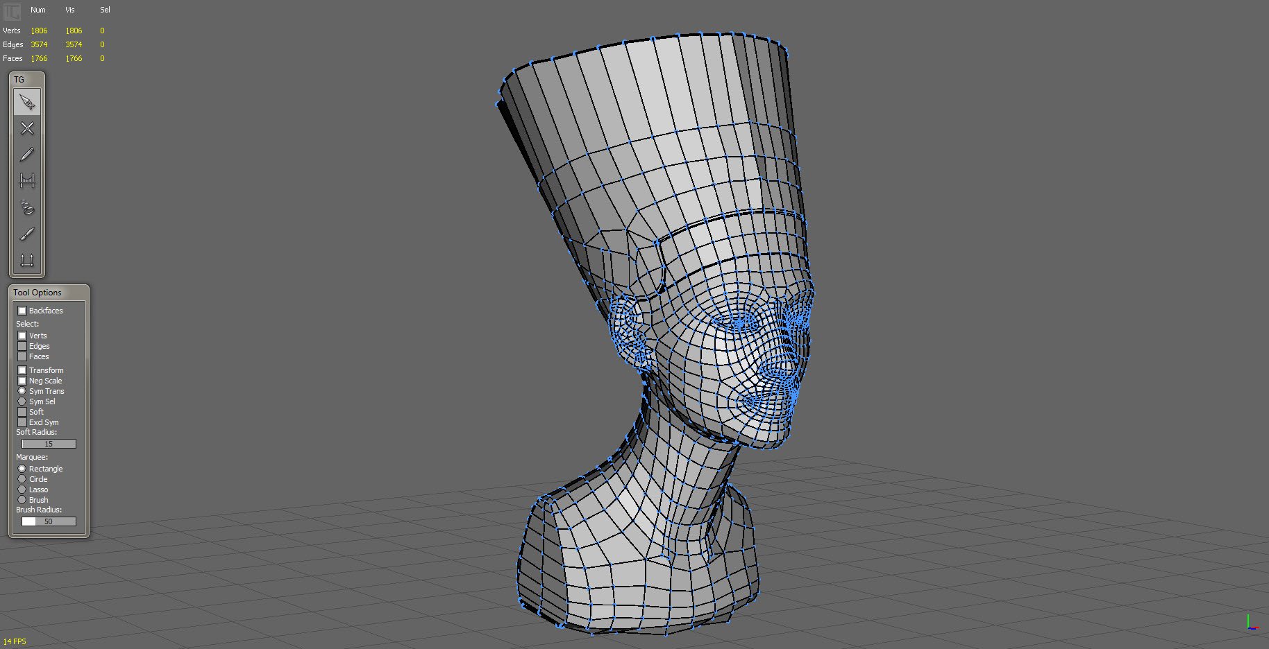
Front view with wireframe overlay
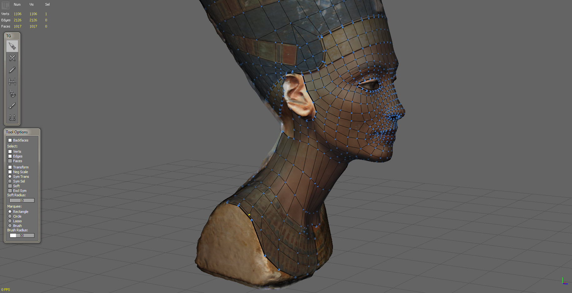
Close-up of face
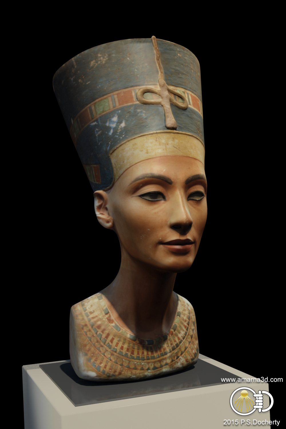
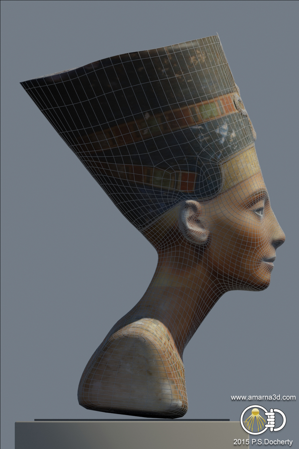
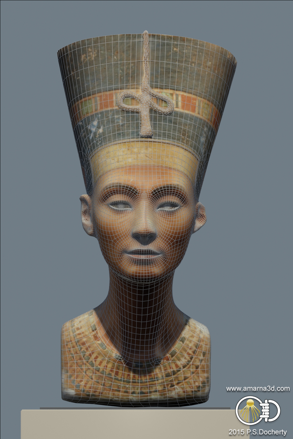
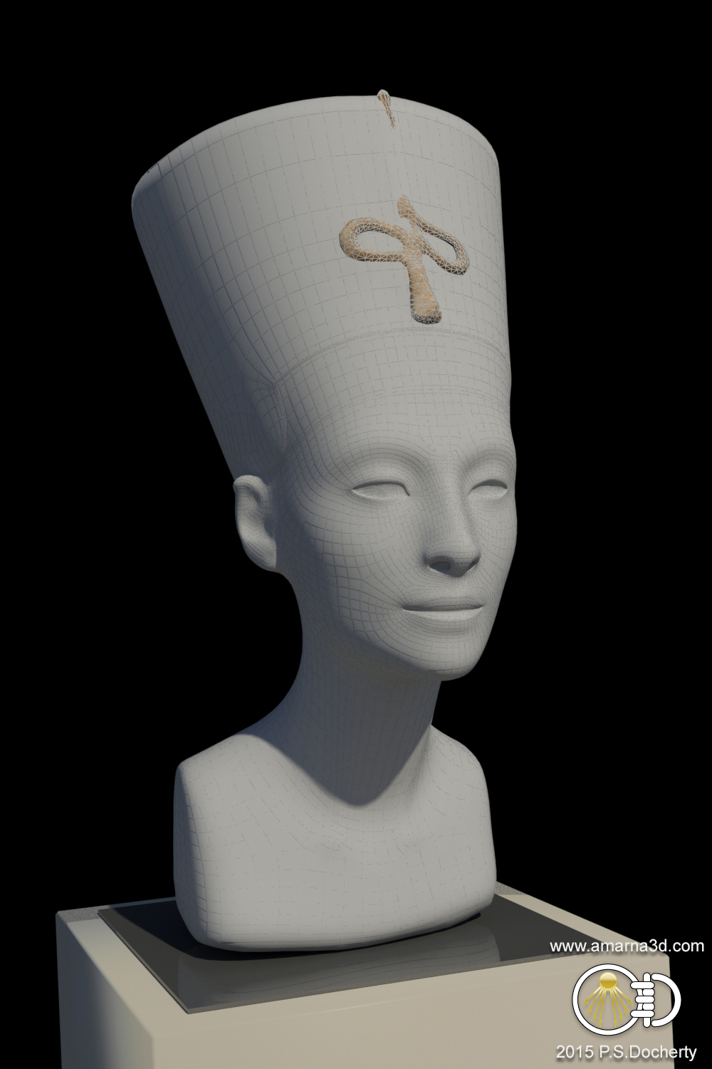
Full view of bust
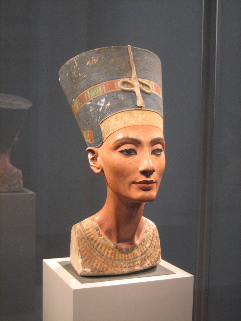
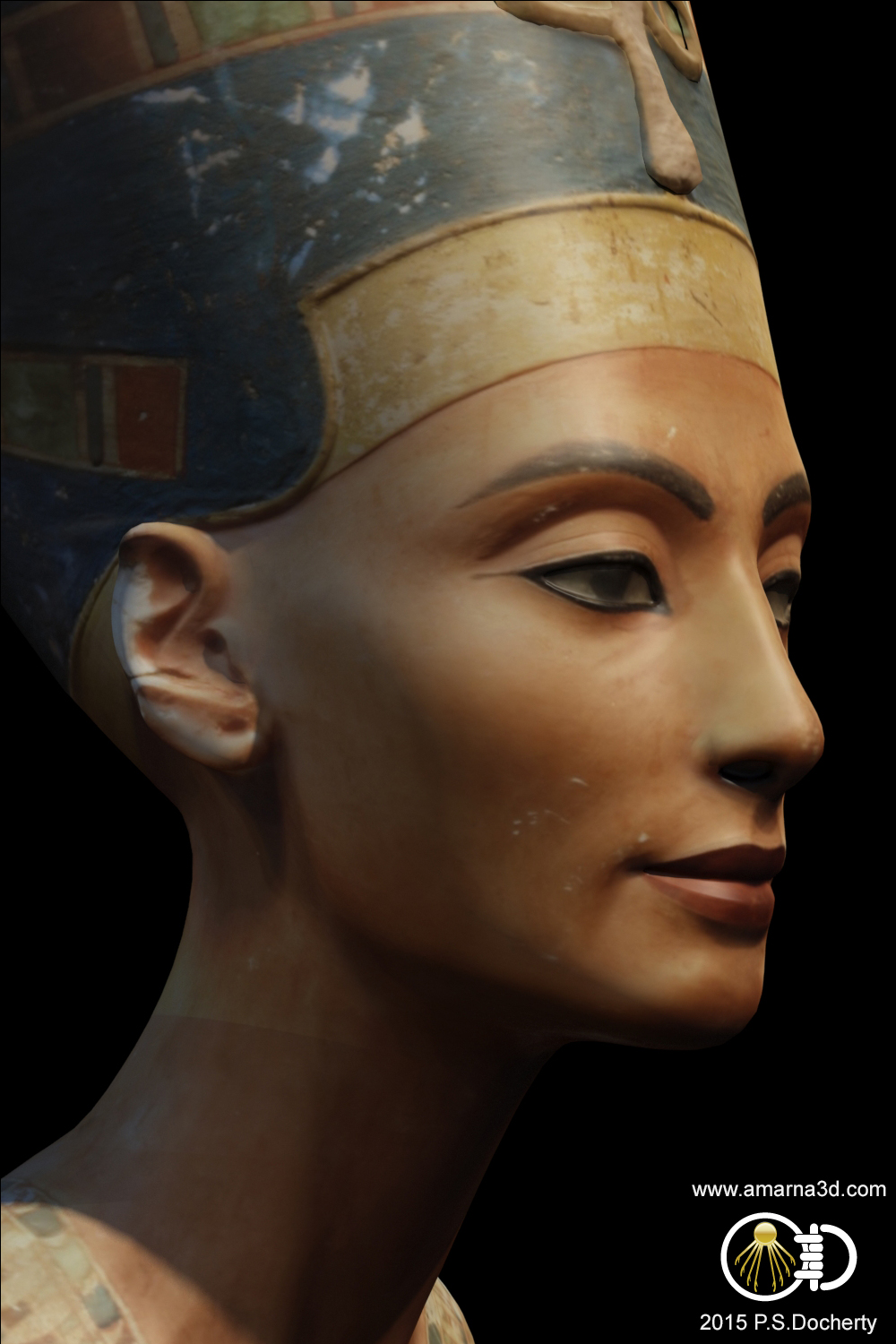
(left & right) Photographs of the original bust
Paul S. Docherty – 15-Feb-2015
This article is originally from my main AMARNA3D website which can be found here.
Introduction
The bust of Nefertiti was originally created around 1340 BC by the Amarna court sculptor Thutmose and was unearthed by the German archaeological team led by Ludwig Borchardt on the 6th of December 1912. It is currently on display in the Neues Museum in Berlin.
The bust is a remarkable work of art showing the full beauty of Nefertiti and the skill of the sculptor. It is thought that the bust was originally created as a template for other sculptors to copy from. This has carried forward into the present and the bust is one of the most copied images from ancient Egypt, making it possibly the most well known alongside the mask of Tutankhamun.
As the initial structure will be based on stereophotogrammetric reconstruction, the construction of the bust will in spirit follow this tradition. This will enable a solid recreation of the model with as much accuracy as possible without actually having access to the original.
")
Using Photogrammetry as a base
Photogrammetry is a well used method of measuring real world features through photographs. When we use photographs to reconstruct the 3D measurements of a surface this is actually referred to as stereophotogrammetry and involves using at least 2 images but more often using in excess of 3. In order to create a 3d representation of an artefact such as the bust of Nefertiti we need to have images that cover all visible areas of the artefact and have an overlap of between 30-50%. The process involves generating feature indexes for each photograph and then cross-matching them with features in the other photographs. This provides positioning of the images in 3D space and allows the camera locations to be determined. The result is a sparse point cloud which represents the initial form of the artefact. A further refinement (Bundle Adjustment) is then calculated for the cameras and a dense point cloud can be generated from the pixels within each photograph. Depending on the accuracy of the camera alignment, and the quality of the photographs, a quite detailed point cloud can be formed. This whole process can be completed using a variety of software applications, with Agisoft Photoscan (commercial) and Visual SfM (open source) being the ones looked at for this project.
Due to their lack of interconnecting faces, point clouds cannot be used very well in other 3d software, so a polygon surface needs to be created in order that further work can be carried out. A free open-source application called MeshLab can do this stage using a surface reconstruction algorithm, poisson or ball pivoting being the most common used, the former giving the best results.
The generated mesh is usually rather noisy across its surface and is still not particularly suitable for normal use. It is necessary to clean up the mesh by smoothing out surface imperfections, removing extraneous elements, and then re-topologising the mesh to give a more organised structure to the surface geometry. This work is usually done through a suite of software tools with Autodesk Mudbox, Autodesk 3dsmax, and Pixelmachine’s Topogun being the applications looked at for this project.
The final stage of construction involves the application of suitable textures applied to the mesh surface to fully represent the colour of the original artefact. This can be done in a number of ways through automatic re-projection within the photogrammetry software, semi-automatic projection within a 3d paint package (Autodesk Mudbox can handle this very well) or 2D hand painting in Adobe Photoshop based on the UV layout of the mesh. The first two methods usually require some touch up by hand.
Overall the construction of the model has some automated processes but invariably it needs human input along the way in order to produce the desired result. We can liken this to a modern equivalent of what Thutmose had his apprentices achieve by developing a guide model for them to use as a basis for future reproduction.
Selection of source images
As Nefertiti has been photographed by so many people there is no short supply of readily available images to be found on the internet. Selecting the most appropriate ones for this project did involve a few general rules, namely:
- Image sharpness – If the images are blurred then the feature match may fail.
- Image resolution – Enough detail needs to be present in each image.
- Coverage – Has the model been covered from all angles?
- Lighting – Shadows cast across the surface may generate false feature indexes which can lead to failure to match. There is also a problem of the model being lit too much or too little which also effects the feature matching.
- Exif data present – By including camera specific information within the image file the photogrammetric software will be able to better estimate measurements internally during the initial image alignment.
- Colour variation – Although not too much of a problem during point cloud generation it can be an issue during the texturing phase.
- Correct image orientation – Sometimes the photographer flips the image for a better composition which obviously affects the feature matching.
- Is it the right model? – Some images may appear to be of the original bust but are in fact photographs of copies and as such the feature match will not register correctly.
The main issue with the collection of source images for this project was the lack of coverage of the rear and top of the bust. Remember it is important to have more than one photograph covering an area and there also needs to be a good overlap for feature matching to take place.
If anyone has some good rear and top views please get in touch.

Some of the images used in the construction. All were found online.
*Original photographic ownership is unclear for these images. If any are identified I will give credit within this article where appropriate.
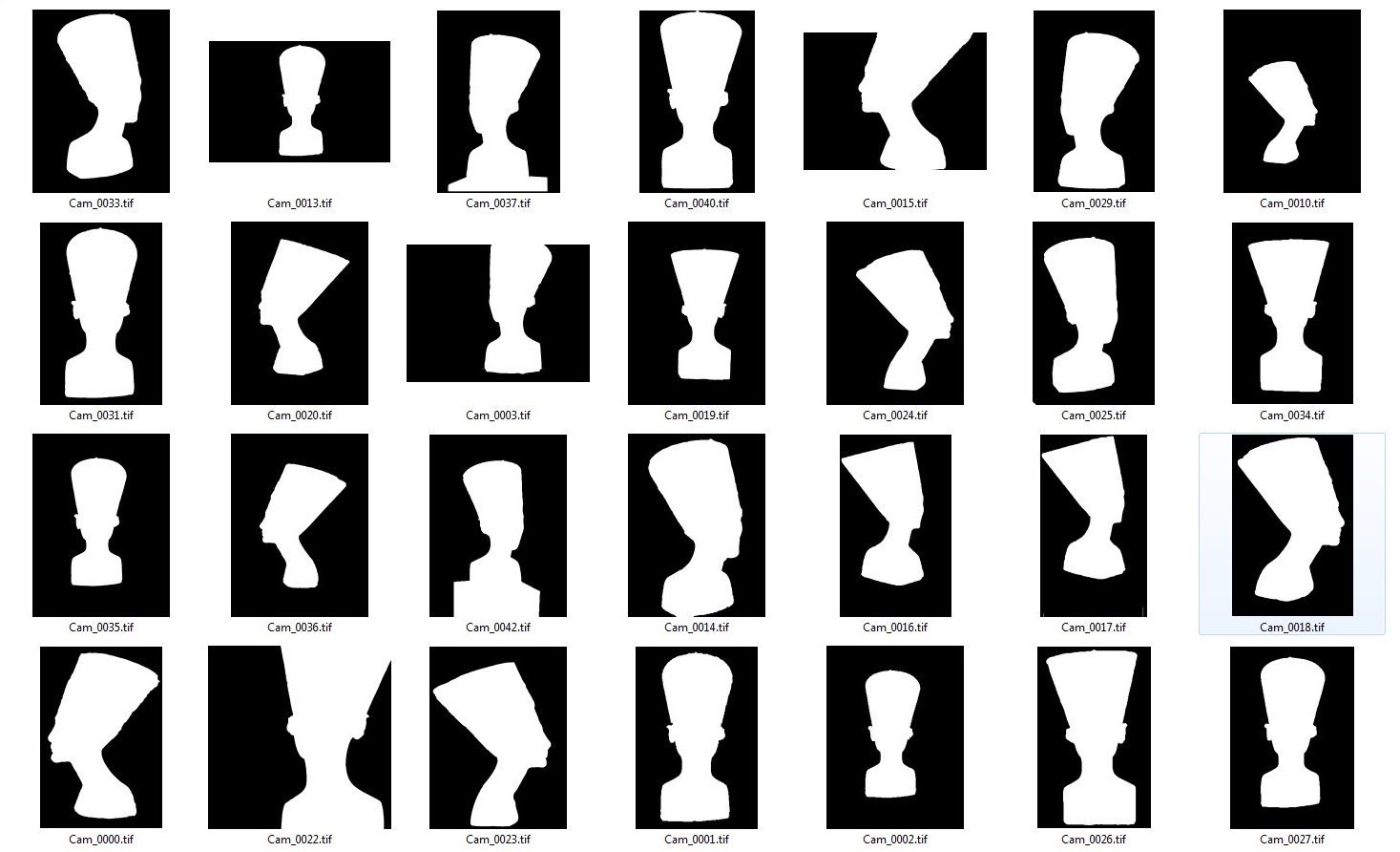
A sample of masks used to remove any details in the original photographs which would skew the camera alignment
Initial camera alignment
Initial experiments with the source photographs resulted in some dismal failures with the sparce point cloud taking on the shape of a space nebula and most definitely not that of Nefertiti.
Working with a small number of images from one viewing direction in order to generate a good base cloud was the next port of call and gradually an increase in photographs slowly moving around the bust began to yield results. At the point where most of the images used resulted in a recognisable point cloud it was realised that the general structure of the sparse cloud was flawed with the back and left side of the bust being distorted.
After a number of experiments it was found that the EXIF image file data may have been causing some internal stress and by removing all EXIF data the sparce point cloud improved dramatically with most of the bust error free but leaving a vertical strip at the rear where no point cloud was generated. This was always known to be a likely issue as there were limited images covering that region.
By removing the EXIF data for the photographs which actually had that information the software defaulted to all cameras having an effective 35mm lens.
Point cloud editing and mesh reconstruction
The initial sparce point clouds were generally quite good but did have some erroneous points which when removed made the dense point cloud reconstruction much more accurate.
The dense point cloud was then examined and cleaned up by deleting any clusters known to be noise. Any distortions present at the rear of the bust were also removed in order to gain the cleanest possible mesh reconstruction.
At this stage the point cloud can be given the correct scale by placing marker points at known positions and setting the distance manually within the software. For this project it was known that the bust was approximately 19 inches or 50 cm in height so by placing a marker at the base and one at the top of the head and setting the scale to be 50cm meant that the bust would retain the correct scale when transferring between different software packages.
Once the dense point cloud was created a mesh was constructed using the highest density settings possible so that the maximum amount of detail could be included from the point cloud.
Further editing within 3dsmax would mean bridging any gaps and reconstructing any missing features by hand.

Initial camera alignment failure resulting in ‘nebula’ formation

Initial sparce point cloud success
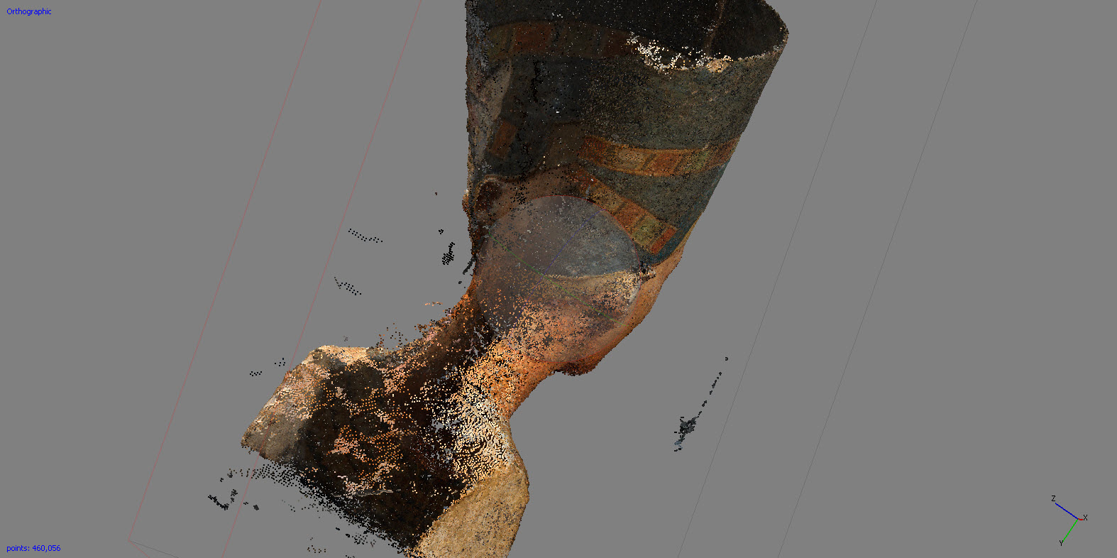
Dense point cloud with missing detail on the back as a result of poor rear view source images

Initial import into Mudbox showing the ‘bubbly’ surface detail generated from noise in the dense point cloud
Mesh clean-up in Mudbox
The resulting mesh was imported into Autodesk Mudbox and the surface was smoothed out gradually to remove the blobby artefacts generated by noise from the point cloud. This process needed a lot of care so that important features were not removed and that the model was not softened too much. When smoothing the surface the brush size would need to be sized appropriate to the area and it was necessary to ensure that the align to surface setting was turned on. This meant that the brush head would orient to the average of the face normals under it and then smooth them flat thereby maintaining the correct surface finish.

Model after smoothing in Mudbox
Initial work in Topogun to create a new clean surface layout
Re-topology in Topogun
Once the model was cleaned up it was then exported out of Mudbox and used as a reference object within Topogun.
Topogun enables the artist to create a new mesh face by face which is aligned to the surface of the reference mesh. This ensures that the new model maintains the original form whilst the surface structure is controlled by the artist. This is where the skill and experience of the artist comes into play in determining the correct flow of edges and polygons. Some small errors can be fixed here but as Topogun is not a fully fledged modelling package there is a limit to the amount of error correction which can be done within it.
Re-topologised mesh ready for further editing in 3dsmax
Final cleaned base mesh in 3dsmax
Final clean-up in 3dsmax
The newly re-topologised mesh is then imported into Autodesk 3dsmax for a final clean-up and correction. All holes are capped and any major missing areas such as the back of the bust are reconstructed by hand using the original photographs as reference. The extent to how much needs to be done by hand is reliant on the original photogrammetric stage and the quality of the point cloud so if more source images of the rear and top of the bust become available then the whole process will be revised.
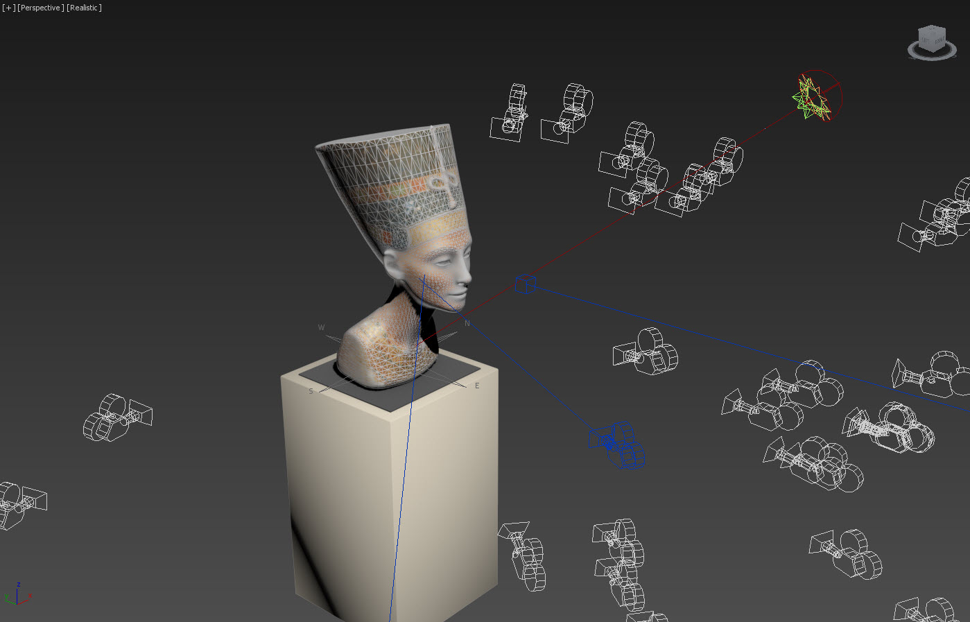
Model in 3dsmax with cameras used for initial photogrammetric construction ready for texture re-projection.

The initial projection from the photogrammetric stage showing irregular shell layout. This needs to be regenerated within 3dsmax in order to be worked further by hand.
Texture Projection
Applying good textures to a mesh is the most important part of the process and can make or break the model even if the mesh is of high quality.
There are a number of ways this can be approached but the method used here was to import the model into the photogrammetry software and use the cameras to re-project the photographs onto the surface. This process takes the orientation of each polygon face and determines which camera it is best aligned towards and stores that projection as a texture. Once all the faces have a texture the software balances out the colour so that there are no patches formed. This is why it is important to ensure that the source images have similar lighting conditions.
Another method is to use the dense point cloud to splatter the mesh surface with colour derived from each point. During the generation of the dense point cloud each point takes the colour of the intersecting pixels projected from the photographs and averages them out so the point cloud has a very good representation of the surface colour. This works only as well as the density of points; too little and the resulting texture doesn’t have the right resolution. By projecting the photographs directly onto the polygon faces you can have a resulting texture which is as good as the source images.
The final texture map when viewed in a 2d editor such as Adobe Photoshop reveals the UV shells can be spread in a non friendly way for post editing by hand. If this is the case then the mesh can be UV mapped within 3dsmax and another texture projection can be done to bake the original texture map onto the newly mapped surface. Wether this is necessary is down to the artist and wether the surface texture needs further work to refine it.
The initial texture projection map with added work on the top of the crown
Final thoughts
As you can see whilst this project does have a focus on automation at the start this is largely to develop a base form for reconstruction by hand. The artist still has a place in the process and this can be quite a large part to play. As accuracy was the driving force behind this project the photogrammetric phase was a great help and not only allowed for better accuracy than could have been gained by hand but also resulted in the construction time being kept to a minimum.
I hope that it can be seen how useful this approach is and that the results are quite impressive. This method certainly has its place within the whole Amarna3d project but the main construction of the city will unfortunately not benefit from it…